When you need to interface with 5V accessories from a 3.3V board you need a Logic Level Shifter.
I used this for my WS2812 Christmas Lights project being controlled by an Arty S7-50.
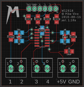
The logic level of the Arty is 3.3V and the WS2812’s require 5V. This post on adafruit shows the requisite wiring for using a 74AHCT125 chip. I used Eagle to design a custom PCB to convert a PMOD interface (single row) to up to 4 separate WS2812 driver circuits.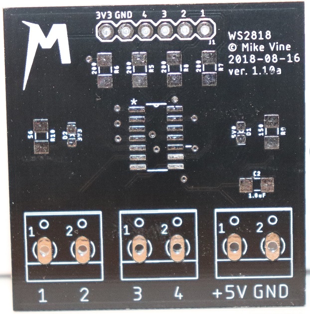
The Eagle files are available here. I ordered them from the very reasonable Chinese PCB manufacturer PCBWay. They had excellent service and were very cheap, the only complaint was that the postage took a while to get to the UK but I did opt for the cheapest postage so can’t complain too loudly. If you are truly lazy you can click here to auto order them from PCBWay. No warranty is given – use at your own risk.
As well as the signals from the FPGA which go into the PMOD header (4, 3, 2, 1) at the top, you must also connect the GND pin at the top to the FPGA, and optionally the 3v3 pin at the top to the FPGA’s 3.3v rail. If you use standard PMOD this will be done for you.
Then connect the +5.0v and GND which power your LEDs to the terminal block in the bottom right.
Once you’ve done that, any 3v3 signals you pass into the input signals (4, 3, 2, 1) at the top are level shifted to 5.0v at the terminal blocks at the bottom.
BOM is:
1x 0.1″ or 2.54mm right angle connector (6 x 1). Like this
4x 1206 200ohm SMD resistors (R5 to R8)
4x 1206 4.7K ohm SMD pullup resistors (R1 to R4, back of board).
1x 0.1uF 1206 SMD capacitor (C1, back of board)
1x 1.0uF 1206 SMD capacitor (C2)
3x 0.2″/5mm 2 pin terminal block connector. Like this.
1x SN74AHCT125D IC (IC1)
OPTIONAL – power LEDs:
1x 1.25mm x 1.4mm SMD power LED (D2, shows the PMODs is connected)
1x 1206 SMD resistor for above LED (R10)
1x 1.25mm x 1.4mm SMD external power LED (D1)
1x 1206 SMD resistor for the above LED (R9)
I used a 2.2v, 20mA LED for the PMOD power LED (D2) and so using a LED resistor calculator like this one (source 3.3v, diode voltage 2.2v, diode current 20mA) I need a 56ohm resistor – hence R10 is marked 56ohm.
Similarly for the 5.0v power LED (D1) I used a 2.2v/20mA LED and using the calculator again (source 5.0v, diode 2.2v, current 20mA) I need a 150ohm resistor – hence R9 is marked 150ohm.
If you used different LEDs than the ones above, obviously run your own numbers through the LED resistor calculator and change R9 and R10 appropriately.